Phase 2 : The adaption of the tower and mounting a HF antenna
To facilate maintenance of the different antennas and since the height of a beam for HF is not as important as it is for VHF and UHF purposes, the top element of the tower (6 meter) was removed, resulting in a total remaining tower height of 18 meter. To achieve this, all antennas had to be removed previously.
All pictures on this page were taken on October 27th and 28th, 1997.
 |
 |
|
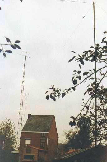
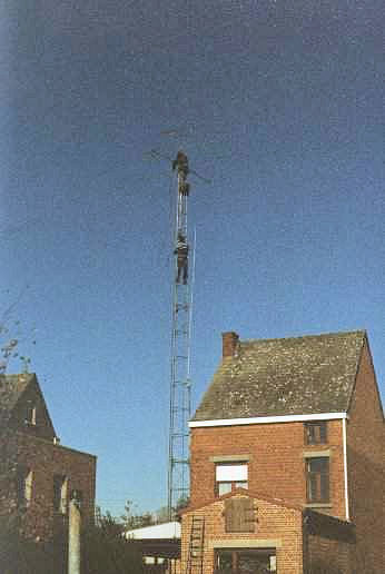
The antenne installation before starting. Notice the yagi antennas and the attached FD4 dipole for HF. |
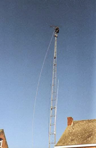
First, all antennas had to be removed. The poor picture quality is due to the bad weather conditions. |
|
 |
||
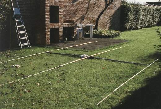
| The Hy-Gain TH3JR 3-band beam, assembled and waiting to be mounted ... | ||
 |
 |
|
The upper 6 m part is removed from the tower. |
Installation of the beam on top of the tower. |
|
 |
 |
|
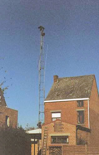
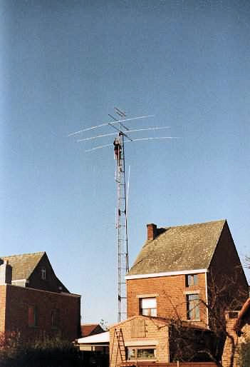
All antennas have been remounted and attached to the corresponding coax cables. |
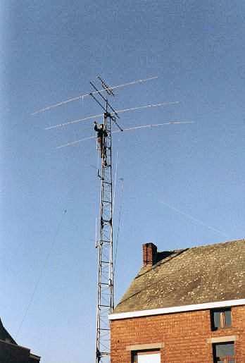
The different dipole antennas (some of them home-brewed) are re-attached to the tower. |
|
 |
||
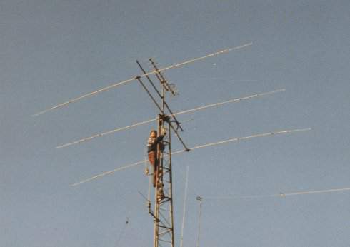
| A last inspection of the top and then everything is set to be used ! | ||
Phase 1 : Erection of a tower with a height of 24 meter and mounting of the VHF and UHF beams and omnidirectional antennas
Phase 2 : Removal of the upper part of the tower and mounting of a 3 element HF beam for 10, 15 and 20 meter
Phase 3 : Replacing the 3 element beam by a 7 element Cushcraft beam for 10, 15 and 20 meter